by Greg Michaelson
Greg Michaelson is an Emeritus professor of computer science at Heriot-Watt University in Edinburgh. He is also a novelist and a short story writer. He wrote this story for CS4FN.
From the cs4fn archive.

“Come on!” called Alice, taking the coat off the peg. “We’re going to be late!”
“Do I have to?” said Henry, emerging from the front room.
“Yes,” said Alice, handing him the coat. “Of course you have to go. Here. Put this on.”
“But we’re playing,” said Henry, wrestling with the sleeves.
“Too bad,” said Alice, straightening the jacket and zipping it up. “It’ll still be there when we get back.”
“Not if someone knocks it over,” said Henry, picking up a small model dinosaur from the hall table. “Like last time. Why can’t we have electric games like you did?”
“Electronic games,” said Alice, doing up her buttons. “Not electric. No one has them anymore. You know that.”
“Were they really digital?” asked Henry, fiddling with the dinosaur.
“Yes,” said Alice, putting on her hat. “Of course they were digital.”
“But the telephone’s all right,” said Henry.
“Yes,” said Alice, checking her makeup in the mirror. “It’s analogue.”
“And radio. And record players. And tape recorders. And television,” said Henry.
“They’re all analogue now,” said Alice, putting the compact back into her handbag. “Anything analogue’s fine. Just not digital. Stop wasting time! We’ll be late.”
“Why does it matter if we’re late?” asked Henry, walking the dinosaur up and down the hall table.
“They’ll notice,” said Alice. “We don’t want to get another warning. Put that away. Come on.”
“Why don’t the others have to go?” asked Henry, palming the dinosaur.
“They went last Sunday,” said Alice, opening the front door. “You said you didn’t want to go. We agreed I’d take you today instead.”
“Och, granny, it’s so boring…” said Henry.
They left the house and walked briskly to the end of the street. Then they crossed the deserted park, following the central path towards the squat neo-classical stone building on the far side.
“Get a move on!” said Alice, quickening the pace. “We really are going to be late.”
————————-
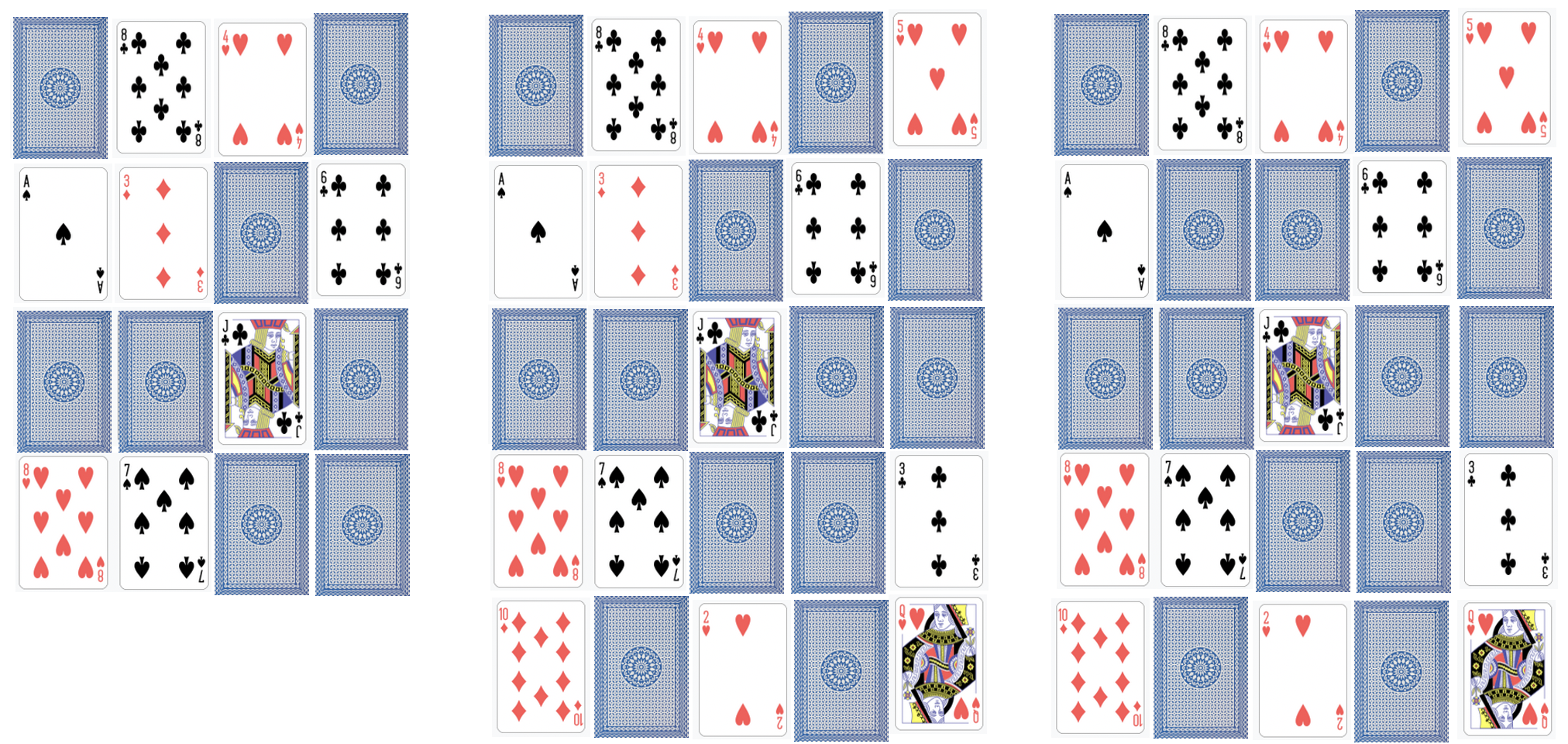
Henry really hadn’t paid enough attention at school. He knew that Turing Machines were named for Alan Turing, the first Martyr of the Digital Age. And he knew that a Turing Machine could work out sums, a bit like a school child doing arithmetic. Only instead of a pad of paper and a pencil, a Turing Machine used a tape of cells. And instead of rows of numbers and pluses and minuses on a page, a Turing Machine could only put one letter on each cell, though it could change a letter without having to actually rub it out. And instead of moving between different places on a piece of paper whenever it wanted to, and maybe doodling in between the sums, a Turing Machine could only move the tape left and right one cell at a time. But just like a school child getting another pad from the teacher when they ran out of paper, the Turing Machine could somehow add another empty cell whenever it got to the end of the tape.
————————-
When they reached the building, they mounted the stone staircase and entered the antechamber through the central pillars. Just inside the doorway, Alice gave their identity cards to the uniformed guard.
“I see you’re a regular,” she said approvingly to Alice, checking the ledger. “But you’re not,” sternly to Henry.
Henry stared at his shoes.
“Don’t leave it so long, next time,” said the guard, handing the cards back to Alice. “In you go. They’re about to start. Try not to make too much noise.”
Hand in hand, Alice and Henry walked down the broad corridor towards the central shrine. On either side, glass cases housed electronic equipment. Computers. Printers. Scanners. Mobile phones. Games consoles. Laptops. Flat screen displays.
The corridor walls were lined with black and white photographs. Each picture showed a scene of destitution from the Digital Age.
Shirt sleeved stock brokers slumped in front of screens of plunging share prices. Homeless home owners queued outside a state bank soup kitchen. Sunken eyed organic farmers huddled beside mounds of rotting vegetables. Bulldozers shovelled data farms into land fill. Lines of well armed police faced poorly armed protestors. Bodies in bags lay piled along the walls of the crematorium. Children scavenged for toner cartridges amongst shattered office blocks.
Alice looked straight ahead: the photographs bore terrible memories. Henry dawdled, gazing longingly into the display cases: Gameboy. Playstation. X Box…
“Come on!” said Alice, sotto voce, tugging Henry away from the displays.
At the end of the corridor, they let themselves into the shrine. The hall was full. The hall was quiet.
————————-
Henry was actually quite good at sums, and he knew he could do them because he had rules in his head for adding and subtracting, because he’d learnt his tables. The Turing Machine didn’t have a head at all, but it did have rules which told it what to do next. Groups of rules that did similar things were called states, so all the rules for adding were kept separately from all the rules for subtracting. Every step of a Turing machine sum involved finding a rule in the state it was working on to match the letter on the tape cell it was currently looking at. That rule would tell the Machine how to change the symbol on the tape, which way to move the tape, and maybe to change state to a different set of rules.
————————-
On the dais, lowered the Turing Machine, huge coils of tape links disappearing into the dark wells on either side, the vast frame of the state transition engine filling the rear wall. In front of the Turing Machine, the Minister of State stood at the podium.
“Come in! Come in!” he beamed at Alice and Henry. “There’s lots of space at the front. Don’t be shy.”
Red faced, Alice hurried Henry down the aisle. At the very front of the congregation, they sat down cross legged on the floor beneath the podium.
“My friends,” began the Minister of State. “Welcome. Welcome indeed! Today is a special day. Today, the Machine will change state. But first, let us be silent together. Please rise.”
The Minister of State bowed his head as the congregation shuffled to its feet.
———————–
According to Henry’s teacher, there was a different Turing Machine for every possible sum in the world. The hard bit was working out the rules. That was called programming, but, since the end of the Digital Age, programming was against the law. Unless you were a Minister of State.
————————
“Dear friends,” intoned the Minister of State, after a suitable pause. “We have lived through terrible times. Times when Turing’s vision of equality between human and machine intelligences was perverted by base greed. Times when humans sought to bend intelligent machines to their selfish wills for personal gain. Times when, instead of making useful things that would benefit everybody, humans invented and sold more and more rarefied abstractions from things: shares, bonds, equities, futures, derivatives, options…”
————————
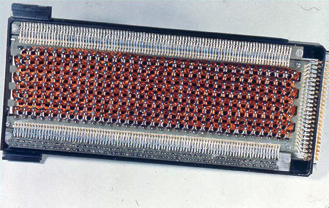
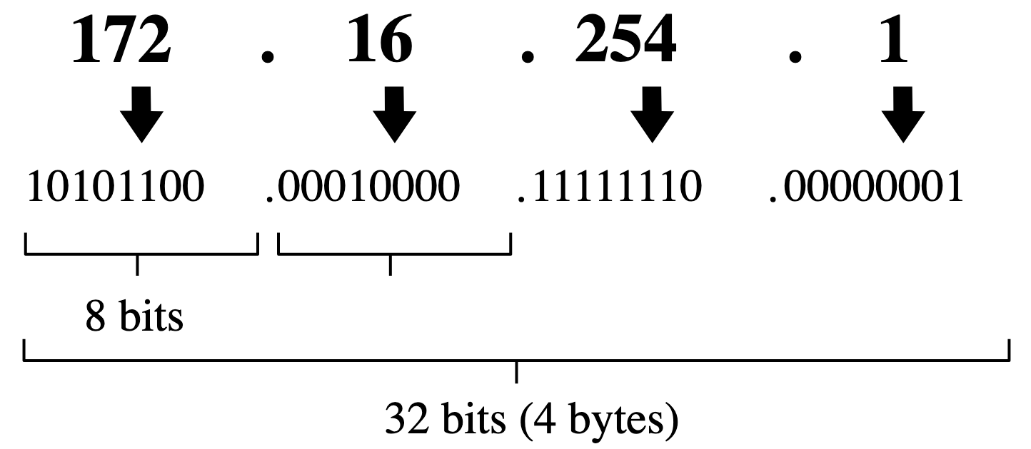
The Turing Machine on the dais was made from wood and brass. It was extremely plain, though highly polished. The tape was like a giant bicycle chain, with holes in the centre of each link. The Machine could plug a peg into a hole to represent a one or pull a peg out to represent a zero. Henry knew that any information could be represented by zeros and ones, but it took an awful lot of them compared with letters.
————————-
“… Soon there were more abstractions than things, and all the wealth embodied in the few things that the people in poor countries still made was stolen away, to feed the abstractions made by the people in the rich countries. None of this would have been possible without computers…”
————————-
The state transition unit that held the rules was extremely complicated. Each rule was a pattern of pegs, laid out in rows on a great big board. A row of spring mounted wooden fingers moved up and down the pegs. When they felt the rule for the symbol on the tape cell link, they could trigger the movement of a peg in or out of the link, and then release the brakes to start up one revolution of the enormous cog wheels that would shift the tape one cell left or right.
————————-
“…With all the computers in the world linked together by the Internet, humans no longer had to think about how to manage things, about how best to use them for the greatest good. Instead, programs that nobody understood anymore made lightening decisions, moving abstractions from low profits to high profits, turning the low profits into losses on the way, never caring how many human lives were ruined…”
————————-
The Turing Machine was powered by a big brass and wooden handle connected to a gear train. The handle needed lots of turns to find and apply the next rule. At the end of the ceremony, the Minister of State would always invite a member of the congregation to come and help him turn the handle. Henry always hoped he’d be chosen.
——————————
“…Turing himself thought that computers would be a force for untold good; that, guided by reason, computers could accomplish anything humans could accomplish. But before his vision could be fully realised, he was persecuted and poisoned by a callous state interested only in secrets and profits. After his death, the computer he helped design was called the Pilot Ace; just as the pilot guides the ship, so the Pilot Ace might have been the best guide for a true Digital Age…”
——————————
Nobody was very sure where all the cells were stored when the Machine wasn’t inspecting them. Nobody was very sure how new cells were added to the ends of the tape. It all happened deep under the dais. Some people actually thought that the tape was infinite, but Henry knew that wasn’t possible as there wasn’t enough wood and brass to make it that long.
——————————
“…But almost sixty years after Turing’s needless death, his beloved universal machines had bankrupted the nations of the world one by one, reducing their peoples to a lowest common denominator of abject misery. Of course, the few people that benefited from the trade in abstractions tried to make sure that they weren’t affected but eventually even they succumbed…”
——————————
Nobody seemed to know what the Turing Machine on the dais was actually computing. Well, the Minister of State must have known. And Turing had never expected anyone to actually build a real Turing Machine with real moving parts. Turing’s machine was a thought experiment for exploring what could and couldn’t be done by following rules to process sequences of symbols.
——————————
“…For a while, everything stopped. There were power shortages. There were food shortages. There were medical shortages. People rioted. Cities burned. Panicking defence forces used lethal force to suppress the very people they were supposed to protect. And then, slowly, people remembered that it was possible to live without abstractions, by each making things that other people wanted, by making best use of available resources for the common good…”
——————————
The Turing Machine on the dais was itself a symbol of human folly, an object lesson in futility, a salutary reminder that embodying something in symbols didn’t make it real.
——————————
“…My friends, let us not forget the dreadful events we have witnessed. Let us not forget all the good people who have perished so needlessly. Let us not forget the abject folly of abstraction. Let the Turing Machine move one step closer along the path of its unknown computation. Let the Machine change its state, just as we have had to change ours. Please rise.”
The congregation got to their feet and looked expectantly at the Minister of State. The Minister of State slowly inspected the congregation. Finally, his eyes fixed on Henry, fidgeting directly in front of him.
“Young man,” he beamed at Henry. “Come. Join me at the handle. Together we shall show that Machine that we are all its masters.”
Henry looked round at his grandmother.
“Go on,” she mouthed. “Go on.”
Henry walked round to the right end of the dais. As he mounted the wooden stairs, he noticed a second staircase leading down behind the Machine into the bowels of the dais.
“Just here,” said the Minister of State, leading Henry round behind the handle, so they were both facing the congregation. “Take a good grip…”
Henry was still clasping the plastic dinosaur in his right hand. He put the dinosaur on the nearest link of the chain and placed both hands on the worn wooden shaft.
And turn it steadily…”
Henry leant into the handle, which, much to his surprise, moved freely, sweeping the wooden fingers across the pegs of rules on the state transition panel. As the fingers settled on a row of pegs, a brass prod descended from directly above the chain, forcing the wooden peg out of its retaining hole in the central link. Finally, the chain slowly began to shift from left to right, across the front of the Machine, towards Henry and the Minister of State. As the chain moved, the plastic dinosaur toppled over and tumbled down the tape well.
“Oh no!” cried Henry, letting go of the handle. Utterly nonplussed, the Minister of State stood and stared as Henry peered into the shaft, rushed to the back of the Machine and hurried down the stairs into the gloom.
A faint blue glow came from the far side of the space under the dais. Henry cautiously approached the glow, which seemed to come from a small rectangular source, partly obscured by someone in front of it.
“Please,” said Henry. “Have you seen my dinosaur?”
“Hang on!” said a female voice.
The woman stood up and lit a candle. Looking round, Henry could now see that the space was festooned with wires, leading into electric motors driving belts connected to the Turing Machine. The space was implausibly small. There was no room for a finite tape of any length at all, let alone an infinite one.
“Where are all the tape cells?” asked Henry, puzzled.
“We only need two spare ones,” said the woman. “When the tape moves, we stick a new cell on one end and take the cell off the other.”
“So what’s the blue light?” asked Henry.
“That’s a computer,” said the woman. “It keeps track of what’s on the tape and controls the Turing Machine.”
“A real digital computer!” said Henry in wonder. “Does it play games?”
“Oh yes!” said the woman, turning off the monitor as the Minister of State came down the stairs. “What do you think I was doing when you showed up? But don’t tell anyone. Now, let’s find that dinosaur.”
Related Magazines …
More on …
- Alan Turing
- LGBTQ+ Computer Science Greats
- Lego Computer Science (Including how to make a Turing Machine)
Subscribe to be notified whenever we publish a new post to the CS4FN blog.
This blog is funded by EPSRC on research agreement EP/W033615/1.